Introduction
The moment your PC lights up but never shows a display, you face a classic trap. The motherboard is receiving power but not turning on in a meaningful way. LEDs glow and fans may twitch, yet nothing reaches POST. You need a plan that separates standby power from a real start. This guide gives you clear steps that work for home builders and IT pros alike. You will test simple mistakes first, reset firmware, and then run a minimal build outside the case. After that, you will verify power rails, isolate memory and CPU issues, check graphics and monitor paths, and hunt shorts. Each step builds on the last, so you avoid guesswork and protect your hardware.
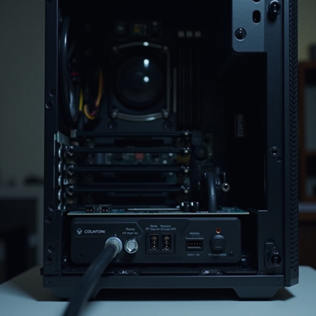
Understanding the Symptom When the Motherboard Is Receiving Power but Not Turning On
What receiving power really means: 5VSB, LEDs, and USB power
Standby power from the PSU 5VSB rail keeps parts of the board awake even when the system looks off. It can light a standby LED, feed RGB controllers, and charge USB devices. That does not prove the system has started. It only proves that the board sees standby power.
POST, display output, and boot are different phases
A successful start moves through phases. The board signals the PSU to start, the PSU stabilizes rails, the board runs POST, and then the system shows video and boots an OS. If power good never arrives or POST halts early, you get no beeps, no debug code, and no video. Knowing which phase fails keeps your testing focused.
Why lights and fans can mislead
Fans can spin because 12 V shows briefly or because a hub backfeeds power. RGB may draw from 5 V standby or its own controller. You might see motion and color even while the CPU power stage is offline or a standoff is shorting the board. Recognizing this avoids false confidence and sets up the next section on safe preparation.
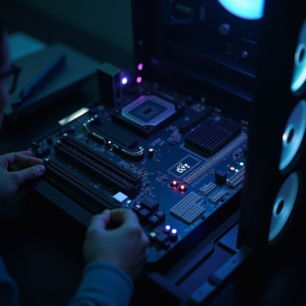
Safety First and Preparation
Electronics do not forgive rushed hands. Before you tug cables or pull a cooler, set up safely so each test produces a clean result. Doing this protects parts and gives you solid evidence for a later support ticket if you need one.
ESD precautions and safe power down
Unplug the PSU. Hold the chassis power button for 10 seconds to discharge. Work on a wood or cardboard surface. Ground yourself by touching the PSU housing while it is plugged into a grounded outlet but switched off. Avoid carpet and static prone clothes. Handle parts by the edges.
Tools you need: speaker, multimeter, USB stick, flashlight
A small beep speaker helps you hear POST codes on boards that support them. A multimeter lets you check rails and continuity. A FAT32 USB drive for BIOS updates saves time. A bright light and phone camera help you inspect pins, pads, and small traces.
Data and warranty considerations
Do not force connectors or overtighten screws. Take photos of cable routing, socket pins, and error LEDs. Keep your component serials handy. If your storage holds critical data, avoid repeated power attempts until you rule out a failing PSU or short. With your workspace ready, move on to fast checks.
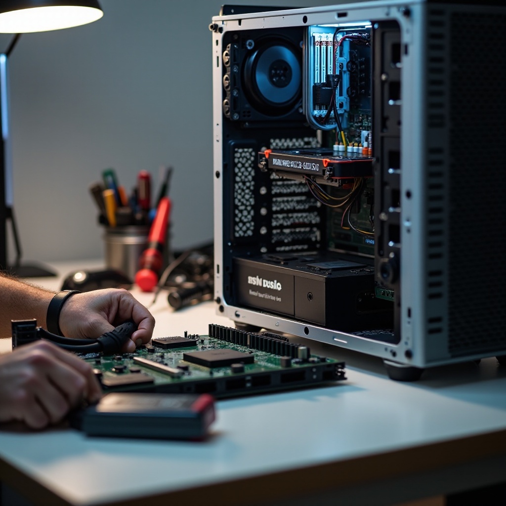
Quick Checks When the Motherboard Receives Power but Will Not Turn On
Start with the easy wins. These checks catch many build issues in minutes and cost nothing. If the system still will not turn on after these, you will be ready to reset firmware.
AC outlet, surge protector, and PSU rocker switch
- Test the wall outlet with a lamp or phone charger
- Bypass surge strips and UPS units for now
- Set the PSU rocker to I and snug the AC cable at both ends
- Verify the PSU input voltage switch if present matches your region
A bad strip or loose cord can make a good build look dead.
Verify 24 pin ATX and 8 pin EPS are fully seated
- Press the 24 pin until the latch clicks into place
- Seat the 8 pin or 8 plus 4 EPS near the CPU socket firmly
- Do not mix PCIe GPU 8 pin cables with EPS; they are keyed differently
- Inspect plastic housings for heat damage or bent latch tabs
An unseated EPS connection is a top cause of lights without POST.
Front panel header and case power switch test
- Confirm the power switch leads sit on the correct header pins
- Polarity does not matter for the momentary switch
- Briefly short the two power pins with a screwdriver to start the board
If the system starts by shorting the pins, replace the case switch or its cable. If quick checks do not fix it, clear the firmware path next.
Clear the Firmware Path: CMOS Reset and BIOS or UEFI Update
When cables and the switch are correct and the board still hangs, reset the platform firmware. This clears bad memory timings, unstable overclocks, and corrupted settings. It also prepares the board for a CPU that needs newer microcode.
Proper CMOS clear by jumper or battery
- Switch off and unplug the PSU, then press the case power button for 10 seconds
- Move the CLR CMOS jumper to the clear position for 10 to 20 seconds, then return it
- If no jumper exists, remove the CR2032 battery for five minutes, then reinstall
This step returns settings to safe defaults and often frees a board stuck in a loop.
Recovering from bad settings and memory training loops
Aggressive XMP or EXPO, tight timings, or undervolts can trap training. After a clear, boot with automatic memory settings. Allow several minutes on the first boot. If it posts, you can re enable memory profiles later with modest voltage and timing margins.
Updating BIOS without boot using USB Flashback
If your CPU launched after your board, it may need a newer BIOS. With USB Flashback, you rename the firmware file as the vendor requires, place it on a FAT32 USB stick, plug into the marked port, and press the Flashback button until its LED blinks. Let it finish. A current BIOS removes many compatibility blockers and sets you up for minimal tests.
Minimal Boot and Breadboarding When the Board Has Power but No POST
If firmware is clean and the symptom persists, remove variables. A minimal build proves the core platform without case shorts or add ons.
Minimal config: CPU, one DIMM, motherboard, PSU, onboard video
Build outside the case with only essentials:
– Motherboard on clean cardboard
– CPU with cooler and fresh paste
– One known good DIMM in the recommended slot, often A2
– PSU with 24 pin and EPS cables connected
– Onboard video to a basic monitor if your CPU supports it
Disconnect GPU, storage, RGB, front USB, and hubs.
Breadboard setup on cardboard and expected signs of life
Place the board on cardboard, connect PSU and monitor, and short the power pins with a screwdriver. Watch debug LEDs, listen for beeps, and look for a logo on screen. If it boots here, the case or an accessory likely caused the fault. If not, you will dig into power, memory, and CPU.
Rebuild methodically, adding one component at a time
When a minimal boot succeeds, add parts in this order and test after each add:
1. Additional memory modules
2. GPU
3. Storage devices
4. Front panel and USB accessories
When failure returns, the last part or its cable is the primary suspect. Now you are ready to diagnose power delivery.
Power Delivery Diagnostics for a Motherboard Receiving Power but Not Turning On
The board can only run POST if the PSU starts cleanly and signals power good. These checks reveal whether your issue comes from the PSU or from the board failing to request power properly.
PS_ON and PWR_OK in plain English
The motherboard pulls PS_ON low to tell the PSU to start. The PSU stabilizes rails and then asserts PWR_OK to the board. If PS_ON never goes low, suspect the power switch circuit, the front panel cable, or the board. If rails spin briefly and shut off without PWR_OK, suspect the PSU.
Paperclip test versus real under load testing
Jumping green to ground with a paperclip only shows that the PSU fan spins without load. It does not prove stable regulation. Use a PSU tester or, better, swap in a known good PSU. If swapping resolves the symptom, replace the original unit. Repeated attempts with a failing PSU risk other parts.
Multimeter checks on 12 V, 5 V, and 3.3 V rails
If you are comfortable with a meter, measure at the 24 pin:
– Yellow wires should read near 12 V
– Red wires near 5 V
– Orange wires near 3.3 V
Probe the 8 pin EPS 12 V during a start attempt. A large sag or no 12 V under load suggests a weak PSU or a short downstream. Stable rails point toward issues with the motherboard or CPU, which you will test next.
Memory and CPU Troubleshooting
With power checked, focus on the components that must initialize first for POST to proceed. Memory training and CPU socket contact issues cause many no POST cases.
Correct DIMM slots and single stick testing
Use the slot the manual prefers for a single stick, often A2. Test one module at a time in that slot. Clean gold contacts with isopropyl alcohol and let them dry. Avoid mixing memory kits; even identical part numbers from different batches can fail to train together. If one module works and another does not, replace the bad module.
Reseat CPU, inspect LGA pins or pads, and check cooler pressure
Remove the cooler and CPU. Inspect the socket with bright light and magnification. Look for bent LGA pins on Intel boards or debris on pads and pins on AMD. Reseat the CPU carefully and apply even cooler pressure. Over tightened coolers can flex the board and break contact. Uneven pressure often triggers DRAM or CPU debug LEDs.
Unsupported CPU and microcode checks
Verify that your board firmware supports your specific CPU model. Check the vendor CPU support list and BIOS notes. If unsupported, update the BIOS with Flashback or borrow a compatible CPU to update. After updating, retest with one DIMM and no extras. If memory and CPU check out, verify the graphics and display chain.
Graphics and Display Chain Sanity Checks
At this point, the platform should at least attempt POST. If you still see no video, remove graphics variables so you can decide whether the issue is GPU, cabling, or board output selection.
Onboard graphics versus discrete GPU testing
If your CPU has an iGPU, remove the discrete GPU and plug the monitor into the motherboard port. If the system posts to the iGPU, the discrete GPU or its power path is likely at fault. If your CPU lacks an iGPU, you must test with a known good GPU.
PCIe power connectors and GPU seating
Seat the GPU until the slot latch clicks. Plug all required PCIe 6 or 8 pin cables directly from the PSU. Many cards need two or more connectors. Avoid splitters and piggybacking on a single rail. Incomplete GPU power often results in fans spinning but no video and a VGA debug LED.
Monitor input, cable type, and port priority
Set the monitor to the correct input manually. Test with a basic HDMI cable, not adapters or docks. Try another display if possible. Some boards default to iGPU when present; you can change that later in BIOS. If video remains absent with both iGPU and a known good GPU, return to short hunting.
Short Circuit and Case Related Culprits
If the platform works on a bench but fails in the case, or if you find intermittent behavior, suspect a mechanical short or backfeed. These faults can mimic bad motherboards and waste hours if you skip this step.
Extra standoffs, IO shield tabs, and loose screws
Confirm that standoffs match mounting holes. Remove any extras that do not align with the board. Check IO shield springs so they touch ports gently rather than folding into them. Look under the board for stray screws or clipped cable ties. Any metal contact where it does not belong can ground a signal pin and stop POST.
M.2 standoffs, fan hubs, and ARGB backfeed
Use the correct M.2 standoff height for each drive. A wrong height can bend the board or short pads. Disconnect powered fan hubs and ARGB controllers during diagnosis. Some hubs backfeed 5 V and create odd LED activity that hides real faults.
USB C front panel header and riser cables
The front USB C header is dense and easy to misalign. A misplugged cable can short pins and block POST. GPU risers or vertical mounts add more failure points; leave them disconnected until the system is stable.
Deciding What to Replace and When to RMA
After methodical tests, your notes should point to a likely part. Use this decision logic to choose a replacement without swapping everything.
Symptom based decision tree: PSU versus board versus CPU versus RAM
- If rails droop or PWR_OK never asserts, replace the PSU
- If a known good PSU and known good RAM still fail after a CPU reseat, suspect the motherboard
- If CPU or socket shows bent pins, no heat output, or consistent CPU LED, suspect the CPU
- If one memory module fails where another succeeds, replace that module or the kit
Document each result so support teams can act quickly.
Documenting tests for support tickets
List each step you performed, the parts involved, and the result. Include photos of CPU socket pins, connector seating, and any burn or discoloration. Note PSU model, age, and the exact behavior of debug LEDs. Short videos of the power on sequence help vendors diagnose quickly.
Protecting your data and other components
Do not continue cycling a suspect PSU. Move storage to another machine for backup before more tests. Use surge protection and avoid hot plugging internal connectors. With your decision made, you can rebuild with confidence.
Preventive Build Checklist for a Reliable System
Now that you have resolved the issue, prevent a repeat. A few habits during assembly and after the first boot keep the platform stable and save time on future upgrades.
Cable management and strain relief
Route heavy cables so they do not pull on the 24 pin or EPS connectors. Use proper length cables from the PSU instead of long extensions. Verify each latch after final routing. Avoid trapping cables under the motherboard where they can press into solder joints.
First boot procedure and BIOS baseline
Boot with a minimal setup first. Update to a stable BIOS. Load optimized defaults and confirm a clean POST. Enable XMP or EXPO only after a successful baseline. Run a short stress test for CPU and memory before installing side panels and adding peripherals.
Surge protection and maintenance cadence
Use a quality surge protector or a line interactive UPS. Clean dust filters regularly. Review system logs after storms for power errors. Replace aging PSUs before they fail under load. These habits reduce the chance that you face the motherboard receiving power but not turning on problem again.
Conclusion
A motherboard receiving power but not turning on usually means the board has standby power but never completes a real start. The cure is a clear, step by step process. You verified outlets and cables, reset firmware, and proved the platform with a minimal build. You checked PSU signals and rails, then confirmed memory seating and CPU contact. You validated graphics and display paths and removed shorts caused by cases, standoffs, and accessory cables. Finally, you used a simple decision tree to choose the right component to replace and documented evidence for support. With patience and a plan, most lights but no POST issues resolve fast and stay fixed.
Frequently Asked Questions
Why do my fans spin and RGB light up but there is no display?
Fans and LEDs can run on standby or partial power. That does not prove POST. Reseat 24 pin and EPS, clear CMOS, and try a minimal boot with one DIMM. Test with a known good PSU and a simple HDMI cable.
Can a dead CMOS battery stop a PC from turning on?
A flat CR2032 rarely blocks startup but it can cause training loops and clock resets. If you cleared CMOS and still see loops, replace the battery and retest. Most no POST cases trace to power, shorts, or compatibility.
How do I know if my motherboard is dead or if it is the PSU?
Swap in a known good PSU first. If symptoms remain, breadboard with CPU and one DIMM. Stable rails with no POST and no beep point to the motherboard. Rail sag or missing power good points to the PSU.